Boat Dual Battery Switch
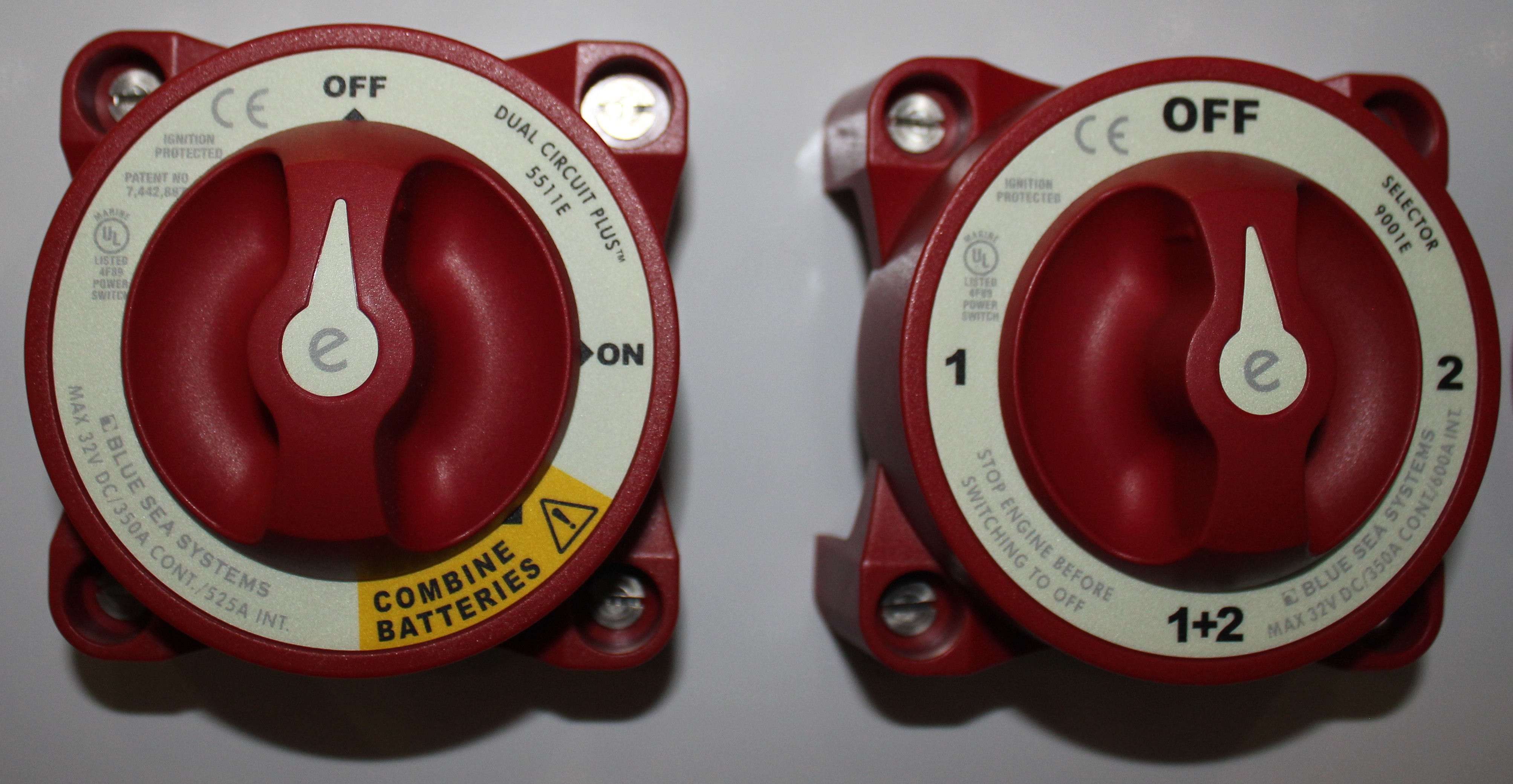
The boat dual battery switch, battery master switch or as it is also sometimes called a boat battery changeover switch, and is that familiar large and usually red multi-position switch that is somewhat standard on many boats. It has become standard largely due to the combined starting charging system configuration that is used on virtually all engines.
In this basic configuration, the charging and starting circuits share the same cabling from the batteries to the engine, so that the engine starter motor takes electrical current in one direction from the batteries through the master switch. Once started the alternator supplies current back to the batteries via the master switch in the opposite direction. The negative return is also a bi-directional conductor is a single cable that is installed from the engine block to the battery bank negative terminal. This same negative conductor also has an additional role as an polarizing conductor that uses the mass of then engine to do so.
Boat
Dual Battery Switch
The boat dual battery switch or basic master switch consists of 3 positions and an <OFF> position. Effectively it is two switches using a common output point. The center position marked <BOTH> <1 + 2> connects in parallel both the connected batteries or battery banks, so effectively they all become one larger battery bank. The battery switch has 3 large terminals at the rear to terminate the positive supply cable from each of the batteries. Many battery switches also still have an advance field disconnect switch that was originally available for connecting an alternator field circuit. The purpose of this was for when turning the master switch to the off position and this isolated and de-energized the alternator field circuit before actual main circuit switching so as to avoid accidental damage to the alternator diodes. This feature is somewhat redundant and I have rarely seen it used as all modern engine alternators have integral voltage regulators and not external ones as they used to be. This was a practical measure when voltage regulators where separate and mounted external to the engine. This article was extracted from my book The Marine Electrical and Electronics Bible 4th Edition, click on the link to get your copy.
Boat
Dual Battery Switch
In operation when transferring from <Position 1> to the center position <BOTH> <1 + 2> and then to <Position 2> the main sliding contacts are make-before-break. This means that there is no (or should be no) momentary break in the circuit that would otherwise create an alternator diode damaging voltage surge and spike. Some boats use a simple <On-Off> type master switch. Usually, two are used with one on the engine and one on the house battery supply. In these cases, a third bridging switch is used for emergency parallel of the battery banks. The configuration usually has the input side of both switches bridged together. In effect it is a master switch. This does create problems in the charging of the batteries.
Boat Dual Battery Switch - The Problems
Dual battery switches do cause some problems and I have visited many a yacht over the years due to the situations listed below.
Operating the Battery Switch Under Load. You have to use great caution when operating a dual battery changeover switch under charging load conditions. If the contacts don’t make correctly or as is very common, you accidentally switch to the <OFF> position the surge created will probably destroy the alternator rectifier bridge diodes. The voltage transient created can be several hundred volts for just several milliseconds and that is what causes the damage.
Damaging Surges. Many people parallel both batteries in the <BOTH> or <1 + 2> position to start an engine. In many cases the setup is that one battery supplies all the boat electronics and when a large current load is applied to that battery during engine starting, the sensitive electronics power supplies can be damaged by the surge or “brown out” that is created when the voltage initially drops to a low value and then suddenly increases.
Boat Dual Battery Switch - The Problems
High Circuit Resistance. In most cases, the cables must run from the batteries to the switch location and back to the starter motor. This has the effect of introducing unwanted voltage drops into the circuit.
Switch Left in <BOTH> Position. A very common human mistake is to inadvertently leave the battery switch in the <BOTH> or <1 + 2> position and this has the undesirable effect of draining both house services and the engine start battery simultaneously.
Poor Quality Switches. I have frequently come across battery switches that are hot after starting or after charging. This due to an internal high resistance across the sliding contacts which has the effect of reducing starting current and making the engine hard to start or reducing the charging voltage due to the voltage drop so batteries do not charge properly. You should always choose the best quality battery master switch from reputable suppliers such as BlueSea, Perko and Guest to name a few.
The takeaway of this article is to understand the limitations and what situations can arise when improperly used. I personally do not install or recommend installing these switches on any sailboat electrical system, either starting or charging circuits. Elsewhere on this site I talk about system circuit separation and how to improve reliability and redundancy. For those on trailer boats and small power boat where these switches are common make sure you understand the limitations. The boat dual battery switch is common so be sure you understand how they operate.

